RTFM - The Real Time FM synthesizer.
>>>Introduction<<<
Features
FAQ
News:
2016-04-09 Maker Faire bay Area 2016
2016-01-27 Sign of Life
2014/06/09 Control Panel
2014/06/01External input as a Waveform
2014/05/28 Waveforms
2014/05/26 An Interesting "Bug"
2014/05/19 Return to Normalcy
2014/05/12 Correction to Block Diagram
2014/05/09 Location of Altera's boot at Maker Faire
2014/05/07 Maker Faire
2014/05/04 Web_site_update_and_prototype_details.
2014/05/03 RTFM
Send questions and comments to: info@pasde2.com
2016-04-09
Maker Faire Bay Area 2016
I will be at the Maker Faire in the San Francisco Bay Area again this year May 20-22, 2016, in San Mateo, California.
I will be demonstrating the RTFM (Real Time Frequency Modulation) synthesizer along with a simple MIDI sequencer prototype in the Altera** booth.
Feel free to stop by an say hello.
** Note that even though Altera is now part of intel, Altera will have its own booth, separate from intel's main display area.
--
Antoine
#iamintel
2016-01-27
Sign of life
Believe it or not, this project (and this web site) is still alive!
After hibernating for over a year, I recently ported the RTFM synthesizer to the DE1-SoC Cyclone V SoC dev kit, in preparation for some software and hardware upgrades.
I haven't started making use of the dual ARM core Hard Processor System (HPS) yet, so the MIDI software still just runs on the embedded Nios soft processor.
Since the DE1-SoC doesn't have an Arduino compatible connector, I had to replace the MIDI shield and breadboard built MIDI interface.
I build a slightly more permanent circuit on a Perma-Proto PCB from Adafruit with two MIDI inputs from the keyboard and the BCR2000 controller and one MIDI output for feedback to the BCR2000 controller.
DE1-SoC with MIDI Perma-ProtoOn the short term horizon are the implementation in RTFM of two essential performance features: pitch bending and velocity sensitivity, but right now I am working on a simple MIDI sequencer to help me demo the synthesizer (there is a good chance that I'll be at the Bay Area Maker Faire again this year).
2014/06/09
Control Panel
Over the last week or so, I spent most of my RTFM time exploring ideas for the control panel. The synthesizer's parameters can all be controlled by MIDI, but I want to create a nice control panel too. Sometimes it's just more pleasant and/or more efficient to turn a real knob, slide a real fader, or press a real button than to twiddle a virtual one with a mouse or even a touch screen.
A few weeks ago I spotted some encoders that seem particularly well suited for control of MIDI parameter: they have 128 positions per revolution. They have a weird encoding though, so some decoding logic would be necessary. By using a programmable logic device with a high I/O count to do the decoding, the same device could also take care of driving a ring (or bar) of LEDs to indicate visually the parameter value. The same device could also implement some form of communication with the heart of the control panel. I'm thinking simple serial protocol here.
The I/Os on these PLDs have additional interesting properties:
The forward voltage of LEDs varies from just over 1 volt to 2 or 3 volts. So if we chose, for example, red LEDs with a forward voltage of, say, 1.4 volts, and a supply voltage of 2.5V, and we connect two of these LEDs in series, between the power supply rails, the applied voltage (2.5V) will be less than the sum of the forward voltages (2.8V) and only a very small leakage current will flow. Too small a current, in fact, to light up the LEDs, even without a current limiting resistor.
- They can have three states: high, low, and high impedance.
- Their output voltage can be set to 3.3V, 2.5V or 1.8V.
But if the point where the two LEDs are connected together is pulled low (through an appropriate current limiting resistor this time), enough current will flow through the top LED1 to turn it on. Similarly, if the mid point between the LEDs is pull high, the bottom LED2 will light up.
So by rapidly switching between the right combinations of high output, low output or no output (high impedance), one, two or none of the LEDs can appear to be lit. And voilà! Two LEDs controlled from one single tri-state output.
2014/06/01
External input as a Waveform
I have finished implementing support for use of external audio input as an oscillator's "waveform".
Currently the external audio can be used as-is as a carrier's output or it can be used to modulate other oscillators.
Oscillators using external audio as their waveform cannot be frequency modulated. (I do have a few ideas on how that could be done, maybe sometime in the distant future I will try them out.)
A politically correct way to describe my initial results would be that "more experimentation will be required to discover the best uses of this feature".
Simply using the output of an mp3 player to frequency modulate an oscillator doesn't give very interesting results, but if the input came from a single instrument, that could possibly lead to more interesting results, especially if the keyboard is played synchronously to the other instrument. Applying amplitude envelopes to external input could also potentially lead to interesting effects. It feels like we might be getting in the domain of applications more suited for modular synthesizers, though.
In any case, the feature is implemented and the future will tell what usages can be made of it.
2014/05/28
Waveforms
Over the last few days I have implemented support for different waveforms in the hardware part of the RTFM synthesizer. Six waveforms are now supported:
You might wonder what's the difference between "noise" and the "random" waveform.
- sine
- square
- sawtooth ramping up
- sawtooth ramping down
- noise
- random
The "noise" waveform produces a different pseudo-random value for every sample at 48,000 samples per second, regardless of the oscillator's frequency settings. It sounds pretty close to white noise, but I haven't measured its spectrum, I just built a simple pseudo-random number generator and checked that it sounded OK.
When the "random" waveform is selected, a different pseudo-random value is produced for every cycle of the oscillator. For example, if the oscillator frequency is set to play A440, 440 random values will be produced per second. When used at low frequencies this is very similar to the random sample & hold feature of analog synthesizers. At the highest frequencies it starts to resemble the "noise" waveform, but a distinct difference can definitely still be heard as the highest frequency that the oscillators support is less than half of the 48kHz rate at which the "noise" waveform changes (the oscillators' frequencies have to be lower than the Nyquist frequency of 24kHz).
In addition to the six waveforms described above, two "waveform" slots are reserved to enable replacing the oscillator output by a copy of one of two external audio inputs.
I hope to implement support for external audio input in the next few days. I am very curious to hear the effect of using external audio input as a modulation source. But I also need to implement support of the different waveforms in the control software to allow selection of the waveform through MIDI command as that still remains to be done. Right now, I only have access to the new waveforms via hard coded presets, so it makes experimenting with various combinations of waveforms rather tedious.
The new waveforms, with their sharp edges, have rich spectra and sound a bit raw when brought out directly to the output. I expect that they will have great potential when used as modulators, but maybe their harshness will help motivate me to look into implementing some form of digital filtering to soften them up a bit (pun intended).
2014/05/26
An Interesting "Bug"
Whilst experimenting with oscillator self-modulation (AKA feedback in Yamaha parlance), I stumbled upon an unexpected behavior: the oscillator goes silent when the modulation index is increased beyond a certain point. The higher the base frequency of the oscillator, the higher this modulation index silence threshold.
I stumbled upon this behavior, which I assumed to be a bug, in the days before the Maker Faire so I took note of it, but didn't spend much time at all thinking about it.
This morning it hit me that this was actually not the result of a bug in the implementation of the oscillators, but rather a side effect of a feature of my implementation, the feature in question being that the RTFM allows very high modulation indices.
The output of a simple non-modulated carrier can be described as a function of time by the following equation:
(eq1): output(t)=sin( 2π⋅f⋅t )
Where f is the frequency in Hz and t is the time in seconds and π the well known mathematical constant.
To do frequency modulation, we replace f in the previous equation by the sum of a base frequency f1 with the output of second oscillator with a base frequency of f2:
(eq2): f = f1 + I sin(2π⋅f2⋅t )
where I is the modulation index.
The output of a simple FM carrier-modulator pair can thus be described as a function of time by the following equation where we substituted (eq2) for f in (eq 1).
output(t)=sin( 2π⋅( f1 + I sin(2π⋅f2⋅t ) )⋅t )
Where f1 and f2 are the base frequencies of the carrier and modulator respectively.
The value of the sine function varies between -1 and +1 inclusive, so if the modulation index is larger or equal to f1, there will be values of t for which I sin(2π⋅f2⋅t ) = -f1 and thus f1 + I sin(2π⋅f2⋅t ) = 0.
That simply means that there will be times where the frequency is momentarily zero, but as time continues to pass the frequency will be non zero again and things will continue on normally.
That is all fine in the pure mathematical world, but in a digital implementation of oscillators, we can actually get stuck at that zero frequency forever. This comes mostly from two facts, first in the digital domain, we don't keep track of an absolute continuous time, but instead we deal with discrete snapshots in time: samples, and second, we simply compute the next sample from the current state and the parameter values.
For a simple oscillator, the state variable is the phase and the parameter is a phase increment which is directly proportional to the frequency. The phase of the next sample is the sum of the current phase and the increment:
phasen+1 = phasen + increment
The output is simply the sine value for that phase:
outputn+1 = sin( phasen+1)
Similarly to the continuous example, for a discrete time carrier-modulator pair, the increment for the carrier becomes the sum of its base increment with the output of the modulator multiplied by the modulation index. This varies for each sample so we give it an "n" subscript too:
incrementn = increment1 + I sin( phase2n )
Again, for large enough I, and the right value of phase2n,
increment1 + I sin( phase2n ) = 0
So phase1n+1 = phase1n + 0
In self modulation (AKA feedback), phase1 is the same as phase2 so for sample n+2, phase2n+1 will be the same as phase2n so the resulting incrementn will again be zero and the oscillator will be stuck at that phase forever with an effective frequency of zero.
I have not decided yet on how to deal with this behavior, I see a few possibilities:
All these potential solutions have their pros and cons, right now I am leaning towards 1. or 4., I'll think a bit more about it before deciding.
- Do nothing and warn the user that high modulation indices should be avoided in self modulation.
- Limit the maximum modulation index for self modulation oscillators.
- Limit the maximum modulation index for all oscillators.
- Force a non-zero minimum frequency for all oscillators.
I am assuming that the solution that Yamaha implemented in the DX7 is 2. That may not work for the RTFM in which every oscillator can go down to the LFO range of very low frequency and thus would require a very low limit on the modulation index.
Feel free to chime in by writing to info@pasde2.com if you have an opinion or an alternative solution to propose.
2014/05/12Return to Normalcy
With the Maker Faire now behind us, I can go back to experimenting and adding new features, not just focusing on having something stable enough to show.
The Faire went reasonably well, but the RTFM was just one of a handful of projects shown in the Altera booth so it wasn't really in the spotlight. I did get a few interested visitors and some interesting feedback.
Possibly the most important thing that I learned recently, I actually realized on my own in the last couple of days before the Faire. Once I had implemented all the basic features that I wanted for the Faire and after I had ironed out the last significant bugs that I wanted to fix before the show, I had a couple of days left to create a few "presets" to showcase the capabilities of the synthesizer.
I don't have that much experience programing FM synthesizers and creating an interesting patch from scratch is not easy, even with real time control of the parameters. That drove home the fact that it would be really nice to be able to make use of the thousands of sounds that have been created for the DX7 over the years.
Unfortunately, that essentially means a complete re-design of the RTFM to take into account DX7 compatibility from the ground up, making sure all the DX7 parameters can be translated into equivalent RTFM parameters.
I must admit that the reverse engineering aspect of that task is really not appealing to me.
On a more upbeat note, I did a quick experiment tonight, and my code can actually easily run twice as fast as I am currently running it, which means that with minimum changes I could double the polyphony from 96 simultaneous notes to 192.
I haven't tried yet, but I am also confident that I could also double the number of simultaneous timbres from the current 4 to 8 (possibly more).
So, 192 simultaneous notes in 8 different sounds... can you say: "TX-816 on a chip"?
The only problem with increasing the number of simultaneous notes is that you basically lose one bit of dynamic range for the notes each time you double the number of notes. The digital-to-analog converter that I am currently using has 24 bits. S/PDIF also supports 24 bit samples. To be sure not to overflow the 24 bits when the 192 notes are sounding at the same time (without companding), each note's dynamic range has to be limited to 16 bits. That's still more that what the original DX7 and, I believe even the DX7-II had, but maybe I should consider doing like the TX-816 and have multiple independent outputs, to preserve the dynamic range.
This web site is too primitive to accept your comments, but you can still send them by email to info@pasde2.com
2014/05/12
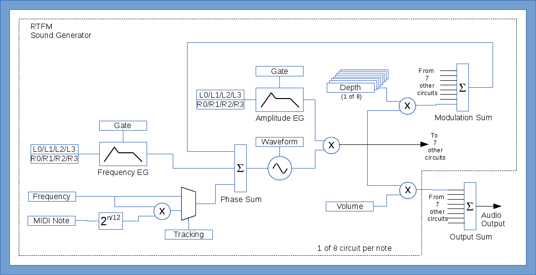
Correction to Block Diagram
I noticed a mistake in the block diagram that I posted in my first post below, so I fixed it. If you are curious you can see the original diagram here. A multiplier was missing between the frequency envelope generator and the phase accumulator. The multiplier is necessary for the envelope generator to affect the frequency proportionally, e.g. to shift up or down by the same musical interval regardless of which note it is affecting. Fortunately I have implemented it correctly, it was just the block diagram that was incorrect.
2014/05/09
Location of Altera's boot at Maker Faire
Altera will have booth 305, just a few booths in when you come in from the east entrance of the Expo HAll.
2014/05/07
Maker Faire
I will be showing the RTFM at the Maker Faire Bay Area in San Mateo on May 17th and 18th in the Altera booth. I invite everybody to come see and hear it.
I will be manning the booth from 2PM to 4PM on both days, and even though I do want to see the rest of the Faire, I should also be stopping by the booth every now and then throughout the day.
2014/05/04
Web site update and prototype details.
Added an FAQ page (still very much in construction) and a Features - present and future page which will be updated as features get proposed, planned and implemented.
The current prototype of the sound generation module is implemented on an Altera Cyclone V GX starter kit board with a SparkFun MIDI Arduino shield and a Parallax Arduino prototyping board (for the second MIDI in port).
The sound generator is designed using the SystemVerilog hardware description language and Altera's Qsys system builder and implemented in a Cyclone V FPGA. The MIDI protocol stack is implemented using the C programming language and runs on a NIOS II processor also inside the Cyclone V device. All the processor's memory is currently implemented in block memory internal to the FPGA but could get moved to external memory if the software becomes too complex or if the sound generator needs the internal block RAMs.
The whole circuit currently runs at 36.864MHz which is 48kHz x 96 x 8 and determines the 96 notes polyphony and the 8 oscillators per note limitation. That clock frequency was chosen as it divides well into 18.432MHz which is the frequency required by the DAC to do 24-bit conversions at 48kHz and also divides well into 6.144MHz the frequency required to do stereo 24-bit at 48kHz over S/PDIF.
The circuit currently has an Fmax of over twice the current operating frequency so it might be possible in the future to further increase the operating frequency and thus the polyphony.
A Behringer BCR2000 midi controller and random keyboards are used as the source of real time MIDI control for the sound generator.
2014/05/03
RTFM
First post!
In this first post I will give a quick overview of my "Real Time Frequency Modulation" synthesizer project, or RTFM for short.
The RTFM is a polyphonic and polytimbral music synthesizer which, as the name suggests uses frequency modulation to create rich dynamic timbres. The sound generation circuits are similar to what is used in Yamaha's DX family of synthesizers with one main difference: all the sound parameters can be changed dynamically while the notes are sounding.
The first objection that people bring up when suggesting real time control of all of an FM synthesizer's sound parameter is: "It doesn't make sense to switch from one algorithm to another." That is true for the architecture of Yamaha's FM synthesizer. What Yamaha calls "algorithms" is the way in which the oscillators (or operators in Yamaha parlance) are connected together, and which oscillator acts as carrier or a modulator.
To avoid the discontinuities that would arise from switching from one "algorithm" to another while a sound is playing, my RTFM synthesizer uses a single universal "algorithm" which allows implementing any and all of Yamaha's algorithms.
The idea is quite simple really, in this universal "algorithm", all the oscillators are carriers and all carriers are modulated by all the oscillators.
To remove one carrier from the sound output, one simply has to set its output volume to zero. Similarly to remove an oscillator from the modulating chain of another oscillator, simply set the modulation depth for that oscillator pair to zero. ( It is simpler than it sounds, I'll try to illustrate this with a picture in a future post.)
Here is a list of the main features of my current RTFM prototype.
- 8 oscillators per note (Yes, two more than Yamaha's famous DX-7 synthesizer. (8 is a nice number to use in hardware circuits.) )
- One Amplitude Envelope Generator per oscillator.
- One Frequency Envelope Generator per oscillator.
- Four Levels / Four Rates Envelope Generators.
- 8 modulation depth control parameters for each oscillator (including self-modulation, AKA feedback).
- One output volume control parameter for each oscillator.
- Each oscillator can have a fixed base frequency or track proportionally to the MIDI note.
- 96 notes polyphony.
- 4 simultaneous timbres (half way between a DX-7 II and a TX-816).
- 48kHz sampling rate.
- 24-bit samples.
- Stereo output.
- Two MIDI in, one MIDI out.
- Hardware implementation of the sound generator.
- Software implementation of the MIDI protocol.
Note that all parameters and features are subject to change at any time.
The text in blue boxes such as, "MIDI Note", "Depth", "L0/L1/L2/L3", etc are the sound parameters that can be controlled in real time.
The following very important performance parameters are not implemented yet. Ironically those are the only parameters that most synthesizers actually do control in real time.
Well that's all for today.
- Velocity.
- Pitch Bend.
- Aftertouch.
- Modulation wheel.
I hope it has piqued your curiosity.
More info to come soon.
For more information contact: info@pasde2.com
All text and illustrations copyright © 2014 Antoine Alary. All rights reserved.


